

Flow mechanism in impeller of centrifugal pump
Flow mechanism in impeller of centrifugal pump
Impeller is the most important part of centrifugal water pump, how does it work? let us to see.
1. Axial vortex
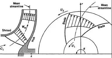
As shown in Figure 1, the actual motion of the fluid in the impeller is approximately considered to be the superposition of the axial vortex motion and the cross flow through different impellers.

The superposition result of the axial vortex is shown in Figure 2. The relative velocity from the working face to the back of blade increases gradually.
2. Blade load
A. Definition
The blade load is defined as the difference between the relative velocity of the working face and the back face of the blade along the blade length direction. As shown in the figure below.
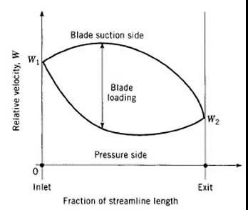
B. According to the research results abroad, it is shown that the blade load is also the basis for qualitative judgment of whether separation flow occurs. The larger the blade load is, the greater the possibility of separation flow and the greater the loss. An excellent impeller generally follows the blade load criterion (from dallenbach 1961), because of the effect of blade load and pressure difference on both sides of the blade, the speed on the working face is lower than that on the back of the corresponding same radius. If the blade load is too large, the relative velocity on the working face may be as low as zero, in which case flow separation is most likely to occur.
Experience shows that W2 / W1 = 0.7 is a critical value. If W2 / W1 = 0.7, the boundary layer may separate. It has important reference value to guide impeller design.
3. "Jet wake" structure
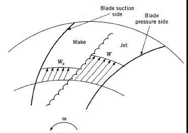
A. In the impeller, when there is flow acceleration or pressure rise, there will be separated flow in the impeller, and along the normal direction from "low energy area" to "high energy area", the "shear layer" or "shunt streamline" is clearly divided into "low energy area" and "high energy area", as shown in the figure below.
B. In the "low energy area" separated from the back of the blade, the flow is stable, but the boundary layer on the working face is unstable, and there is a trend of migration along the rear cover plate of the impeller to the front cover plate. This flow state in the impeller: a stable "separated low-energy area", or the "Wake" structure at the back of the blade, as well as the combination form of the mainstream or the "jet" structure on the working face, is called the "jet wake" structure.
C. For low specific speed centrifugal pump impeller, short blade is usually used to avoid the "jet wake" phenomenon.
D. Foreign research and statistical results show that (from tuzson 1993), according to the following statistical curve of fluid separation in the two blade channel, the lower part of the curve represents the value range of "jet wake" which will not occur, and the upper part represents the range of occurrence.

4. Flow under off design conditions
A. Import flow
The left figure (a) shows the separation of fluid in the working face in the high flow area (Q > QN).
It can be seen from the triangle of inlet side velocity that the direction of relative velocity changes with the increase of axial velocity. The left figure (b) shows the separation of back fluid in the small flow area (Q < QN).

The figure below shows the backflow phenomenon at the impeller inlet under the condition of small flow area (Q < QN) (from tuzson 1983).

B. Flow in impeller and pump body


In Figure 1, the flow in the impeller and volute under off design conditions will return at the inlet and outlet of the impeller.
The second figure below shows the backflow phenomenon at the outlet of mixed flow pump in small flow area. Therefore, it is very important to choose the outlet setting angle of different profile of mixed flow pump.

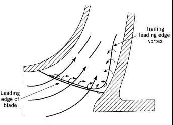
Figure 1 below shows the vortex region in the vortex shell under the condition of small flow area and large flow area.
The second figure is the velocity distribution in the inner section of the volute.


