
Basic Lectures On Overhaul And Maintenance Of Multistage Pumps
Basic Lectures on Overhaul and Maintenance of Multistage Pumps
①. Structure
②. Working principle of multistage pump
③. The principle and function of components
④. Pump maintenance
⑤. Measurement and adjustment of clearance and series volume of multistage pump
⑥. Points to note in the maintenance of multistage pumps

①. Multistage pump structure
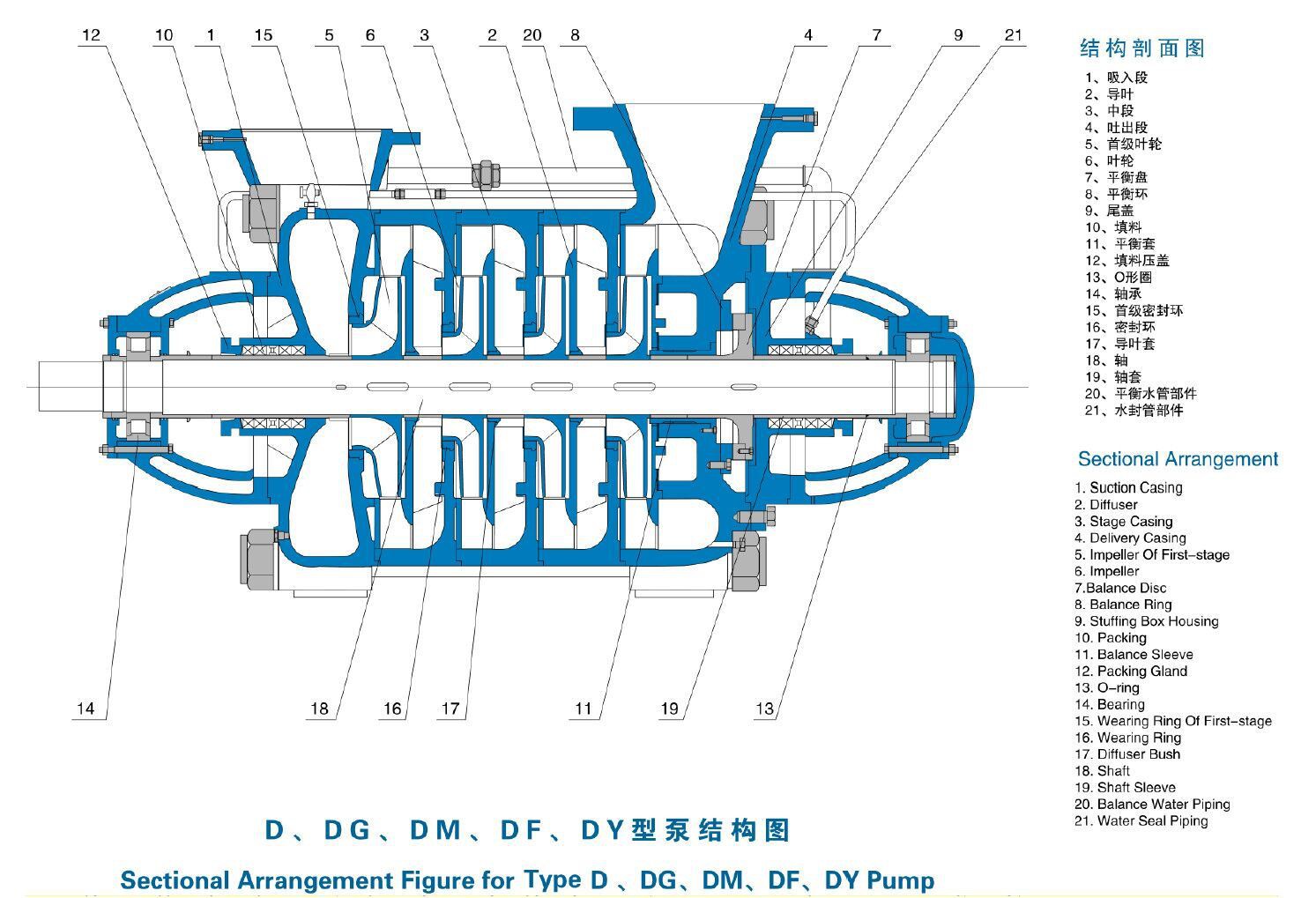
1.The multistage pump is mainly composed of four parts: stator, rotor, bearing and shaft seal
2. The rotor part is mainly composed of shaft, impeller, balance disc, shaft sleeve, etc.
3. The main components are: low-pressure suction section (feeding pipe, feeding chamber); pump body (volute, guide vane, anti-wear ring); high-pressure output end (pump head); balance device (balance pipe, balance plate, Balance plate); sealing device (packing seal, mechanical seal); pump shaft (inter-shaft sleeve, impeller, positioning key, bearing) composition
4. Auxiliary devices: bracket, base, coupling, motor, filter, etc.
②.Working principle of multistage pump
The liquid being transported enters the suction port of the pump under a given pressure. Due to the action of the impeller, the kinetic energy and potential energy of the liquid are increased. After the liquid enters the guide vane, part of the kinetic energy is converted into potential energy (each stage of the impeller is equipped with A guide vane), the opposite vane of the guide vane conveys the liquid to the inlet of the next stage impeller under favorable hydraulic characteristics.
Due to the repetition of this process from one stage to another, each stage increases the same pressure. After passing through the final stage guide vane, the fluid enters the annular chamber of the cylindrical body, and finally enters the discharge pipe through the discharge port. road.
③. The principle and function of components
1. The working principle of the balancing device:
The suction port of the impeller faces the drive end of the pump. The liquid pressure on the rear cover of each stage of the impeller is greater than the liquid pressure at the front cover, and the axial force is very large, generally tens of tons to hundreds of Tons of force, so the pump must have an axial force balancing device to balance the axial force of the pump rotor pointing to the suction end.
The pressurized liquid from the final stage impeller flows into the water chamber between the balance plate and the balance seat through the radial gap between the balance seat and the adjustment sleeve, making the water chamber in a high pressure state. After the balance plate, there is a balance pipe connected to the inlet of the pump, and its pressure is approximately the inlet pressure of the pump. In this way, the pressure on both sides of the balance plate is not equal, and a backward axial balance force is generated. The magnitude of the axial balance force changes with the change of the axial displacement, adjusting the axial gap between the balance plate and the balance seat (that is, changing the pressure of the water chamber between the balance plate and the balance seat) to achieve the purpose of balance. But this balance is often dynamic.
2. Balance of axial force
The measures for balancing the axial force of multistage centrifugal pumps generally include: symmetrical arrangement of impellers, use of balance drum device, balance disc device, and balance drum and balance disc combination. There is also a double-balance drum mechanism (high-pressure water pump). The impeller is symmetrically arranged or the balance drum device is used, the axial force cannot be fully balanced, and thrust bearings are still required to bear the residual axial force. Multistage centrifugal pumps are more balanced by a balance plate with automatic adjustment of the axial force.
The balance drum is a cylinder, which is installed behind the final impeller and rotates with the rotor. A radial gap is formed between the outer surface of the balance drum and the pump body, one end is the high pressure zone of the final stage impeller, and the other end is the low pressure zone connected to the suction port. In this way, the pressure difference acting on the balance drum forms a balance force opposite to the axial force on the impeller, whose size is determined by the diameter of the balance drum. The effect is only to reduce the axial force, but it cannot fully balance the axial force.
3. Balance plate
The balance plate is mostly used in horizontal multistage pumps. It is installed after the final stage impeller and rotates with the rotor. The balance plate generally has two functions:
1. Balance the axial thrust effect
2. Axial positioning
4. Pump casing
The main function of the pump casing is to enclose the impeller in a certain space so that liquid can be sucked in and pressed out by the impeller. The pump casing is mostly made into a volute shape, so it is also called a volute. As the cross-sectional area of the flow channel gradually expands, the high-speed liquid thrown around the impeller gradually reduces its flow rate, so that part of the kinetic energy is effectively converted into static pressure energy. The pump casing not only collects the liquid thrown out by the impeller, but also an energy conversion device.
5. Impeller
The impeller is the core part of the multistage pump. It has a high speed and a large output. The blades on the impeller play a major role. The impeller must pass a static balance experiment before assembly. The inner and outer surfaces of the impeller are required to be smooth to reduce the friction loss of the water flow.
6. Pump spindle
The function is to use the coupling to connect with the motor to transmit the torque of the motor to the impeller, so it is the main part of transmitting mechanical energy. It not only supports all the parts on the rotor, but also bears the role of transmitting torque.
7. Bearing
The bearing is to eliminate axial movement, bear axial load and reduce end face friction. According to the different requirements of the parts, it can be divided into two types of assembly: unit orientation and bidirectional assembly. When assembling, the small inner diameter ring is matched with the transmission shaft, and it rotates together with the transmission shaft; the ring with the large inner diameter is installed on the support sleeve, it has a gap with the transmission shaft, and does not rotate together with the support sleeve. If the installation is reversed, the friction on the end face will increase, thereby losing the role of the thrust bearing
④. Pump maintenance
1. Pump disassembly steps
Issuing maintenance work orders
The maintenance work sheet shall be signed by the operator to confirm that it has reached the necessary conditions for maintenance.
Remove the motor anchor bolts and remove the motor
Take out the coupling wheel.
Check whether the shaft is bent, install a dial indicator to lay down the shaft run.
Remove the bearing parts at both ends.
Remove the mechanical seal and shaft sleeve at both ends.
Remove the balance plate.
Remove each level of guide vanes, impellers, and mouth rings in sections.
When installing and resetting, follow the order of disassembly first, and use appropriate techniques and tools to install each part in turn
2 Precautions for disassembly and assembly during maintenance of multistage pumps
1. When disintegrating:
Before disassembling the thrust bearing, use a dial indicator to measure the balance disc gap and make a record
When disassembling, the parts must be marked in the original assembly order to avoid confusion and wrong assembly during reassembly;
Small parts that are not convenient for marking "such as keys" can be used with the same level of impeller or
When disassembling, you can intuitively feel whether there are abnormal parts, such as loose fit, etc.
2. Installation
Install the rotor first, and perform the dynamic balance test again.
Reinstall the parts in the reverse order of dismantling the pump. When reinstalling, pay attention to remeasure the gap value at each sealing ring to ensure that it is correct.
The total amount of rotor string should be measured before installing the balance plate.
After installing the balance plate, measure the rotor half-string volume.
Tighten the main bolts evenly, paying attention to the corners.
When installing the thrust bearing, pay attention to adjusting the gap of the balance disc, and adjust the gap of the balance disc with the adjusting ring in front of the bearing.
1. Common faults and handling methods:
Fault 1: motor overload
main reason
1. Wrong direction of rotation
2 Foreign matter in the impeller
3. Coaxiality error of the coupling exceeds the allowable value
4. Friction between impeller and pump casing
Approach︰
1. Correct the direction of rotation
2. Inspection and cleaning
3. Re-alignment
4. Adjust the gap between the impeller and the pump casing
Fault 2: The balance pipe and high-pressure end of the centrifugal pump are running hot and the pump pressure drops
Main reason:
1.The balance part is out of function, caused by dry grinding of the balance plate and the balance plate
2.Difficult heat dissipation; bearing damage "poor lubrication conditions" causes the temperature of the pump head to rise;
3.The equipment is not concentric, causing the high-pressure section seal and bearing eccentric wear;
4.The packing seal is too tight, and the allowable leakage is too small to cause the pump to burn
Approach:
1.Check and replace the balance board and correct the operation method;
2.Check and replace the high and low pressure end bearings, and maintain them regularly improve lubrication conditions;
3.Adjust the concentricity;
4.Check whether the sleeve between the shafts is seriously worn, and replace the packing with a new one after the sealing condition;
Fault 3: mechanical seal leakage
Main reason:
1. The pump rotor moves axially, and the moving ring is too late to compensate
2.The operation is unstable, and the pressure in the sealed cavity often changes
3. Periodic rotor vibration
4. The sealing surface of the dynamic and static rings is worn
5. The end surface of the sealing surface has a small specific pressure
6. Sundries in the seal
7. The direction of using the splicing spring is wrong, the spring force is skewed, the spring is blocked or the spring pressure is insufficient
8. The shaft surface has axial grooves or pits or corrosion at the sealing ring
9. The pump shaft is bent
10. The vertical deviation of the sealing surface of the static ring or the moving ring and the shaft is too large
Approach:
1. Adjust the amount of shaft movement
2. Adjustment operation
3. Eliminate vibration
4. Grinding or moving and static rings
5. Adjust the end pressure
6. Remove debris
7. Adjust or replace the spring, adjust the spring compression or replace the spring
8. Repair or replace the bushing
9. Correct or replace the pump shaft
10. Reduce vertical deviation
Fault 4: The balance plate is worn out during the operation of the centrifugal pump, and the pump string exceeds the specified range.
Main reason:
1.The pump volume is not good, too much impurities in the water cause the pump balance plate to wear;
2.Improper assembly, causing the pump shaft to allow the string to be too large or too small;
3.The bearing is worn and the gap becomes larger, which causes the shaft allowable amount to be too large;
4.The motor shaft and the pump shaft are not concentric "producing radial runout, axial runout", causing a series of mechanical damages, causing the balance between the balance plate and the balance plate.
Approach:
1.Stop the pump and replace the balance plate, and check the balance gap;
2.Readjust the assembly gap;
3.Replace the bearing;
4.Adjust the concentricity of the equipment;
Summary
Through this multistage pump overhaul and maintenance training, I mainly talked about six aspects. In fact, everyone can understand from the whole story that our theme has been around the structure of the multistage pump, the signs of failure and the countermeasures. Analysis, such as the silkworm peeling the cocoon, until the goal is reached, we follow this method to carefully analyze the equipment used, without letting go of any clues, you can also draw more accurate conclusions to help further improve the actual combat skills.